

After receiving a Raspberry PI as a gift from RedditGifts (thanks /user/Tikitorch5000!), I decided I would use it to convert a NES into the ultimate retro machine. I was inspired by Lifehacker’s article: http://lifehacker.com/how-to-turn-your-raspberry-pi-into-a-retro-game-console-498561192
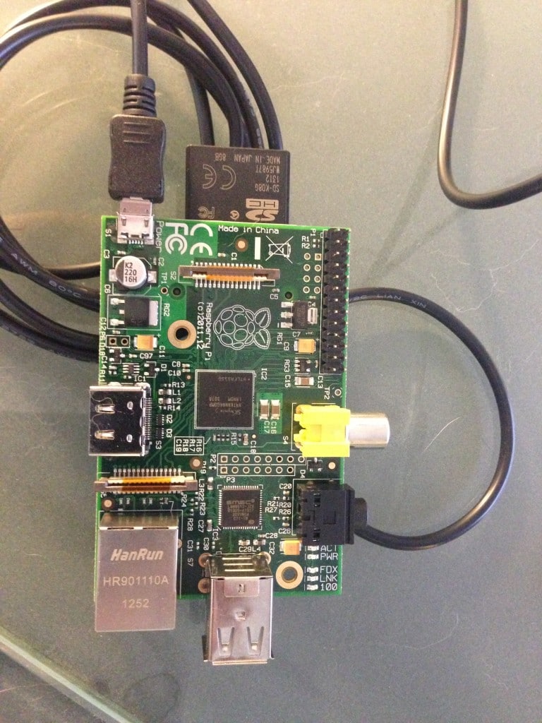
It all started with this. I picked out a 16GB compatible SD card (there’s a list on the Raspberry PI site you can choose from), and loaded up RetroPie, the software mentioned in Lifehacker’s article.
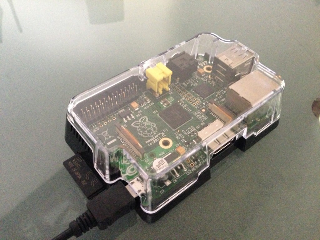
I found a cool enclosure for the PI on Adafruit.com (great website; a few other parts mentioned below were from Adafruit as well). It was only $10 and made it much easier to mount, and kept the sensitive parts on the board from being damaged during the project:
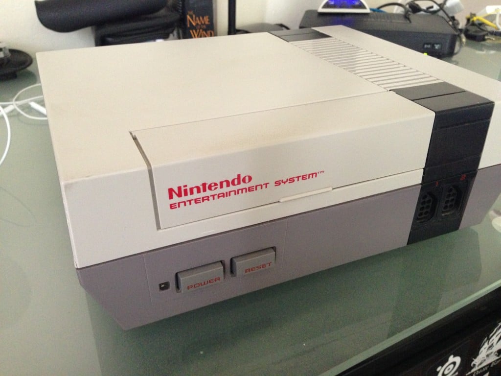
Here’s the NES enclosure I found on eBay. It was sold as-is, as the actual internals didn’t work. That’s perfect, because all I needed was the case, which was in phenomenal condition. The power LED, ports, and switches were still intact.
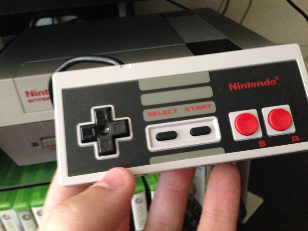
I found a couple of brand new original NES controllers; I read some bad things about the aftermarket ones having cheap buttons, so I wanted the real deal.
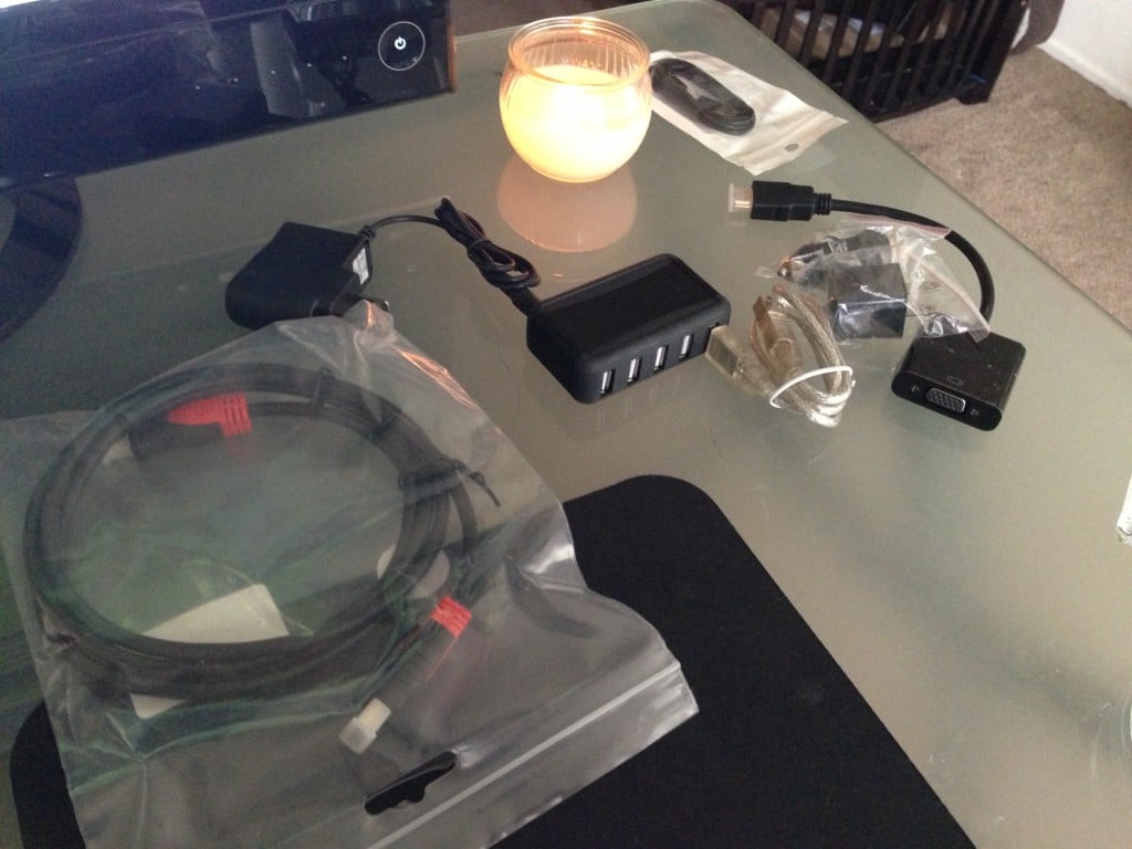
Now I’m getting excited about the project. I picked up a few USB hubs and monitor adapters. The entire system will later be powered by a single USB hub, which we’ll get into more later. For now, I was excited to get this thing up and running.
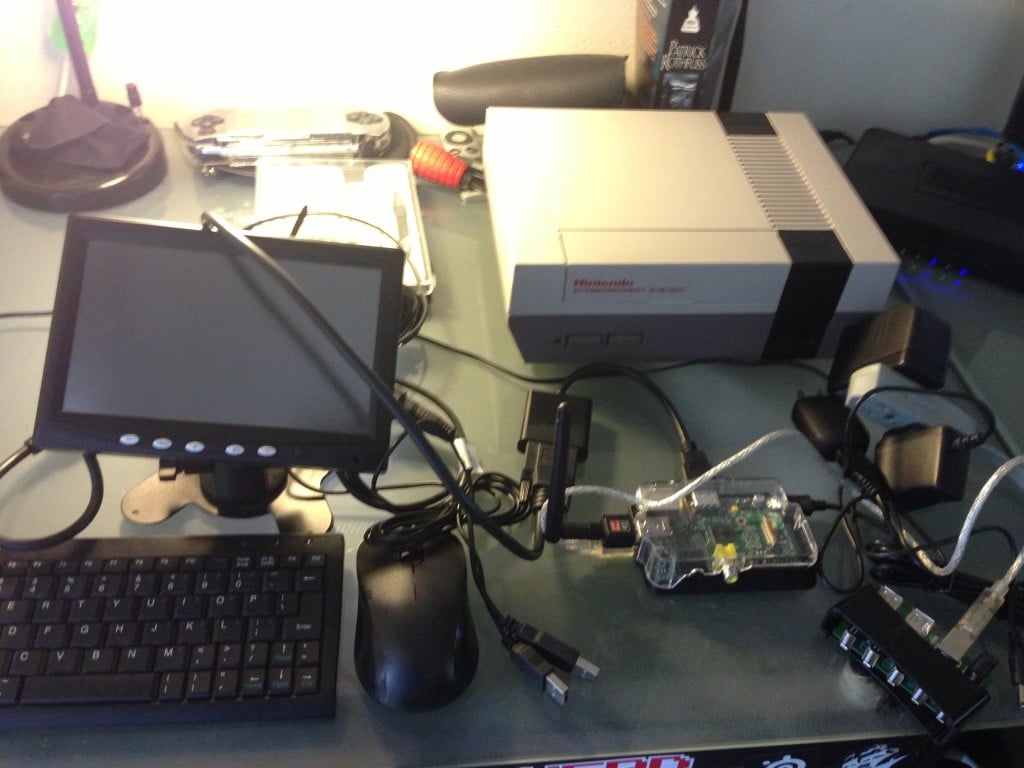
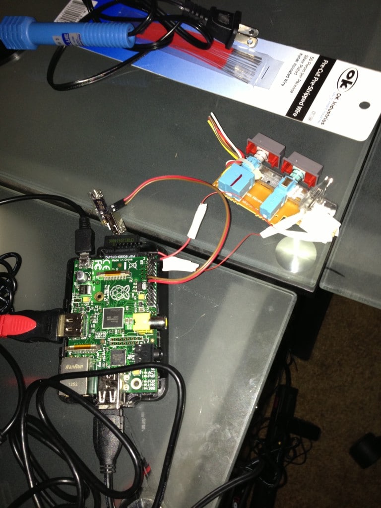
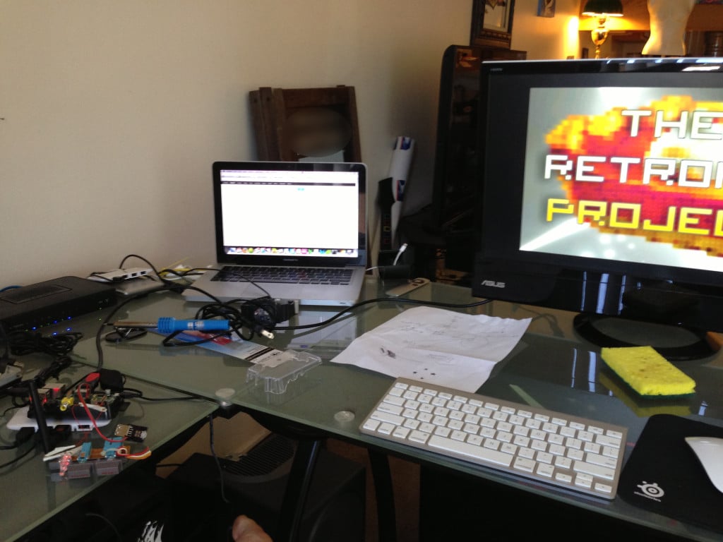
Here’s my first setup, getting it all hooked up to a monitor and testing it out. You’ll see a Wifi-adapter, which I’ll mention next. The NES is still empty, at this point.
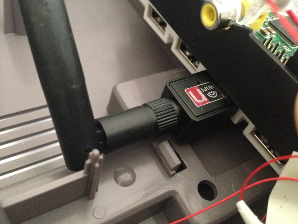
Here’s the Wi-Fi adapter I bought. I found it on eBay; it claimed to be compatible with the Raspberry PI, and it was. That was easy. A Wi-fi adapter allows my NES to connect to my network as soon as I turn it on. This way, I can transfer new games to it wirelessly via SSH.
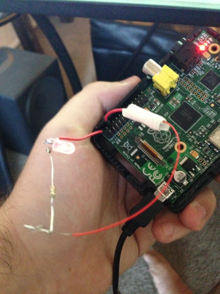
Decided to wire up the LED light on the NES case next, with a 270Ω to 330Ω resistor. It was easier than I thought; I followed this diagram that I found online: http://i.imgur.com/DAHNZ8U.jpg
Next was wiring up the power and reset switches. I found a great little chip by Mausberry Circuits that sent a shutdown signal to the Raspberry PI every time the power switch was released, which made sure that it shutdown safely. Raspberry PI’s don’t like having their power cut suddenly. This little guy made it a breeze to wire the switches up.
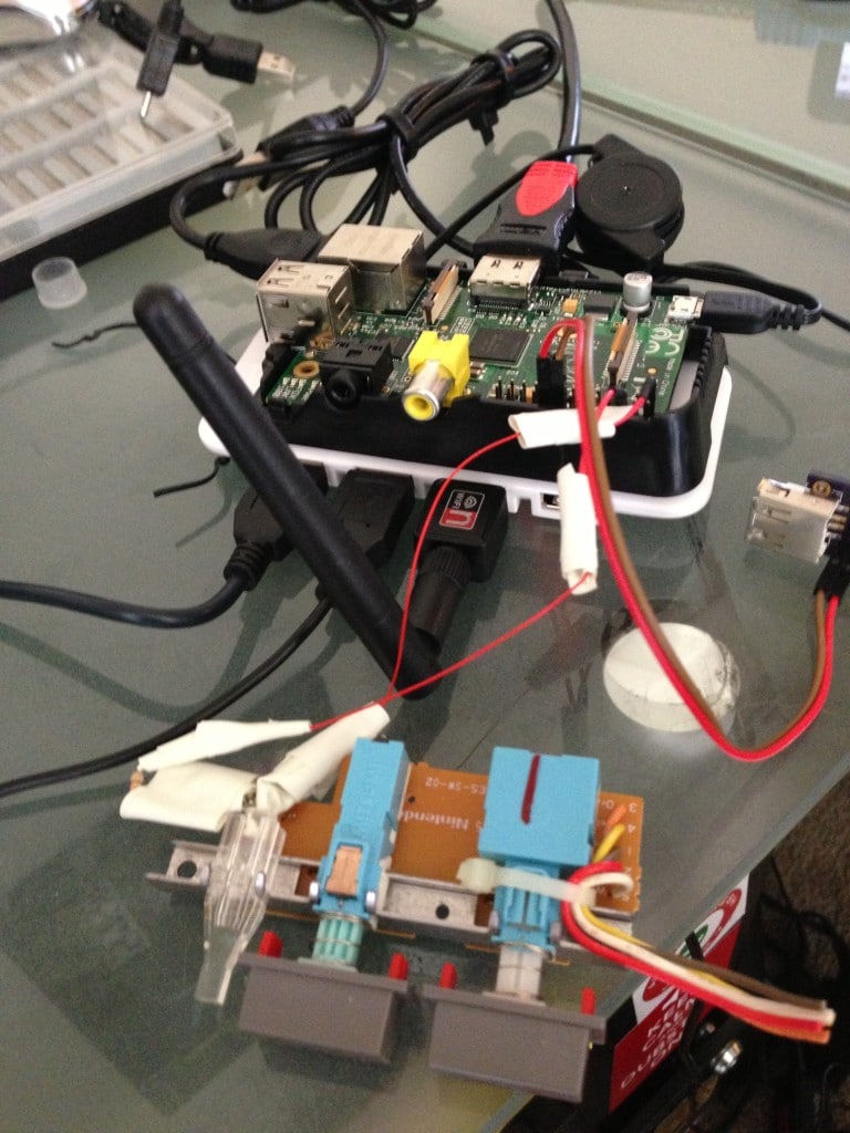
Here’s a pic with both the power switches and the LED wired up to the GPIO pins on the Raspberry PI.
Next, here was the USB hub I decided to run the Raspberry PI from, as well as all of the USB peripherals for the system.
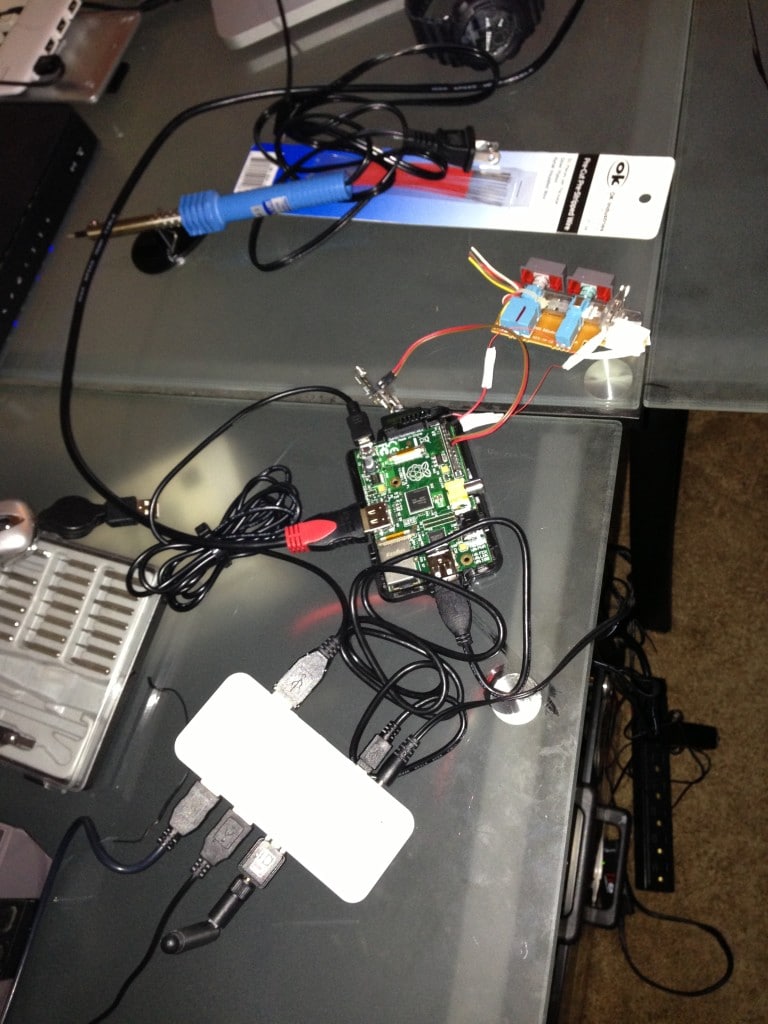
I eventually found it easier to mount the device on top of the USB hub. This would save space in the enclosure later. I just used some velcro so it would be easy to remove if need be.
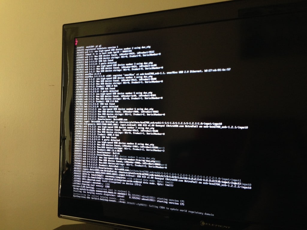
Time to plug it in. Looks like RetroPie boots up just fine.
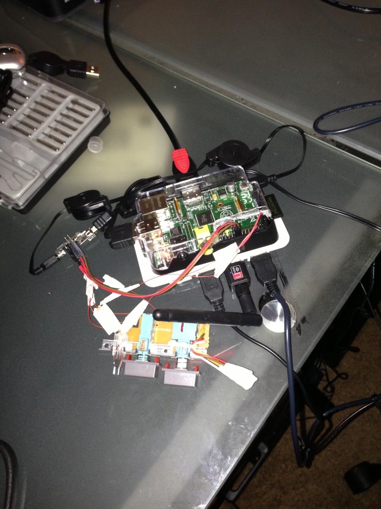
Here’s a closeup of the heart of it. I used a lot of collapsible USB extension cables for the inside of the case, since they are a great space-saver.
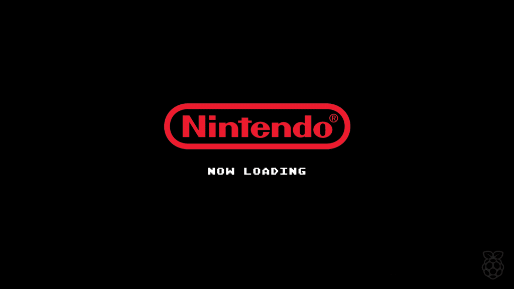
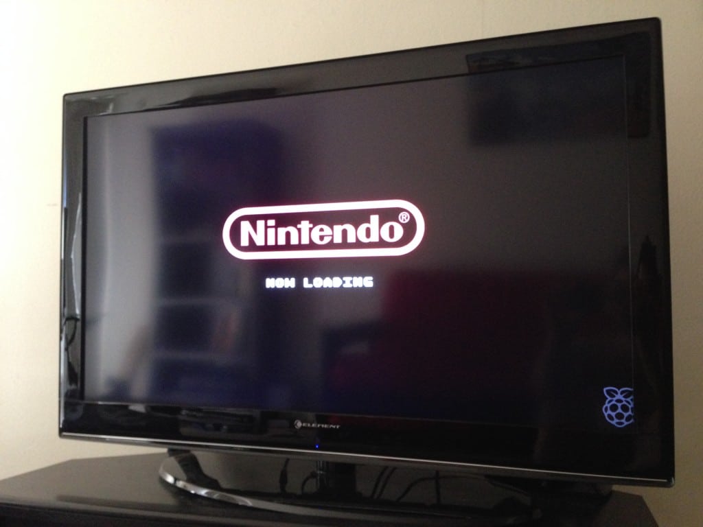
Photoshopped a custom Nintendo Bootscreen for the NES. It’s available here if ya want it.
Time to strip out the NES and get everything settled in. Here’s how it looks with what I’ve done so far in the case:
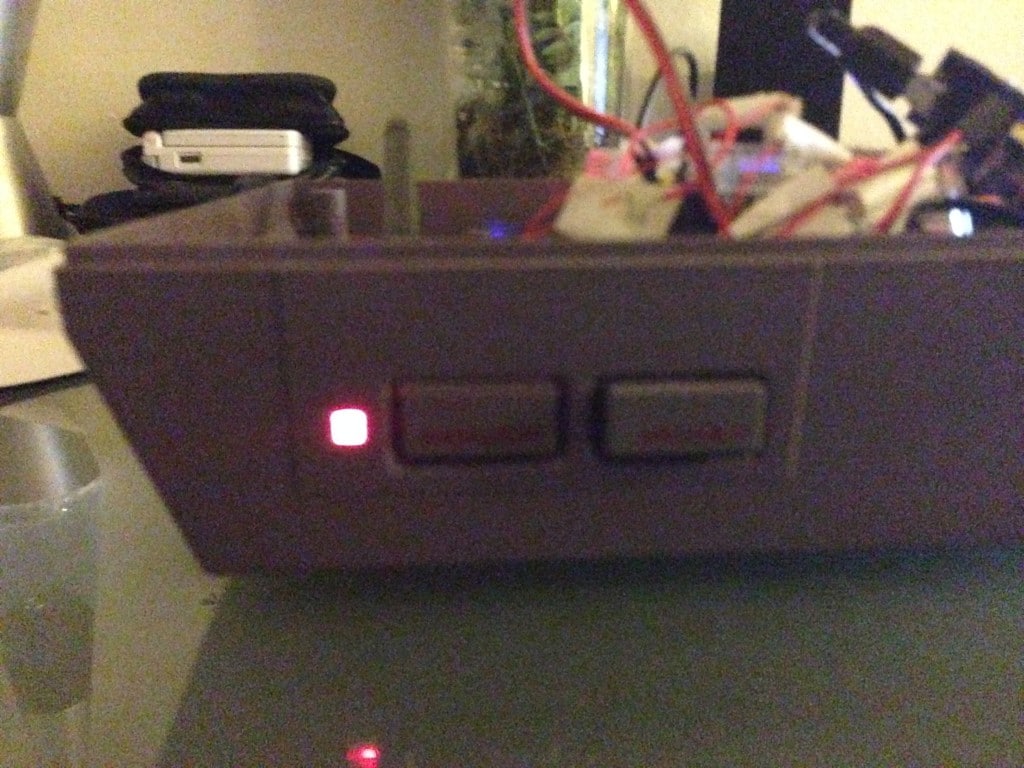
Power LED looks neat.
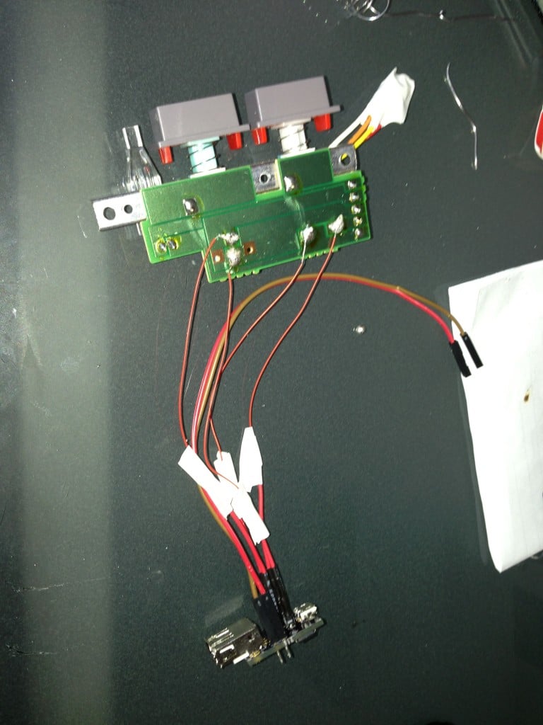
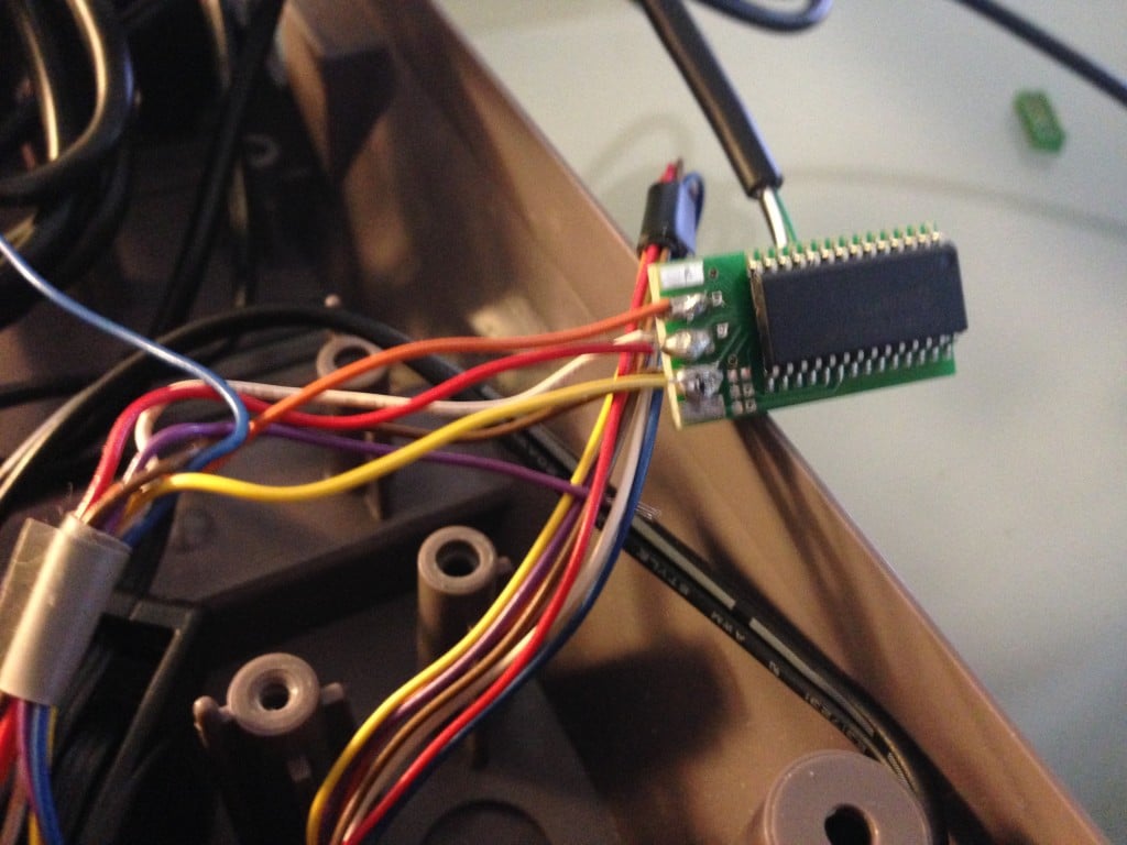
Time to wire up the controller ports. I decided to use the OEM controller ports, and modify them inside the machine to be converted to USB. My goal for this project was to keep it as clean and OEM looking as possible, so this was the best route.
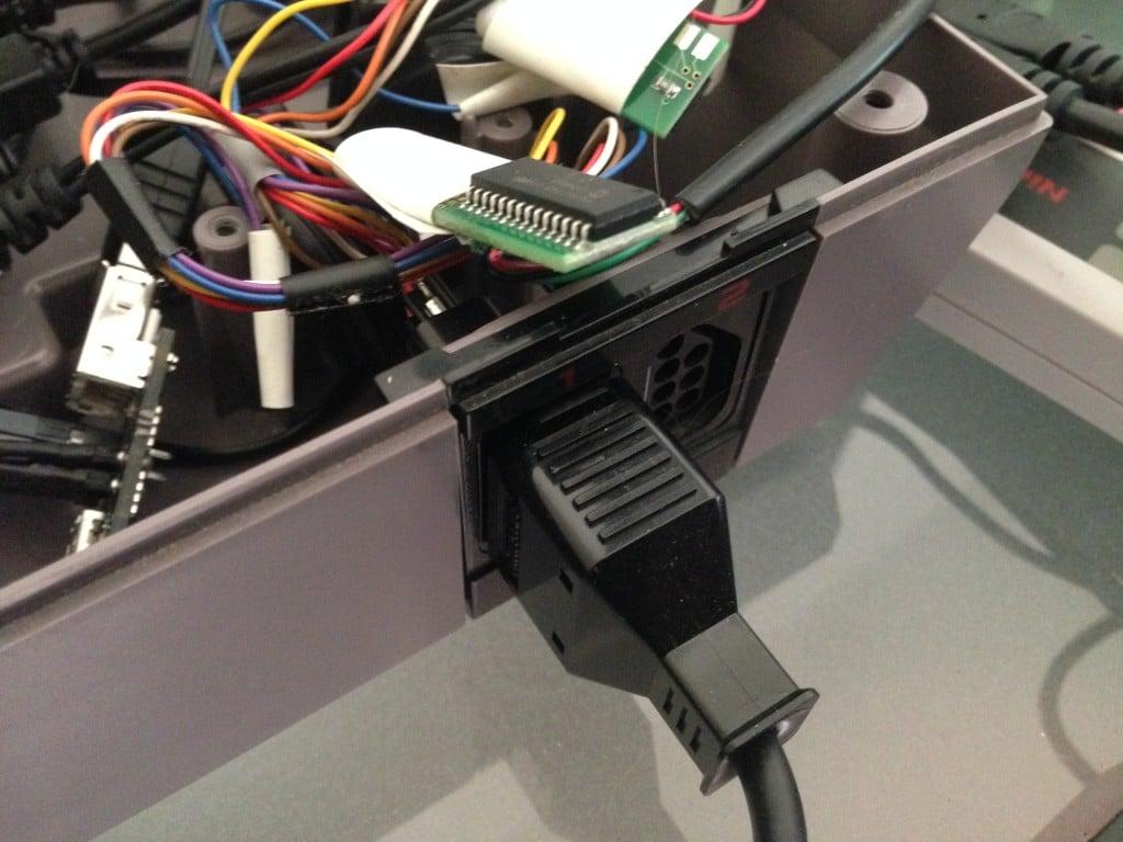
I went with RetroZone’s $25 mod chips to convert the NES ports to USB. Both controllers are wired up! Here’s what the chip looks like:
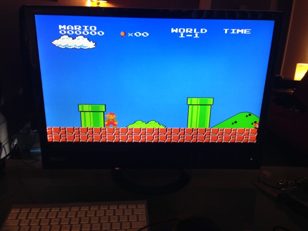
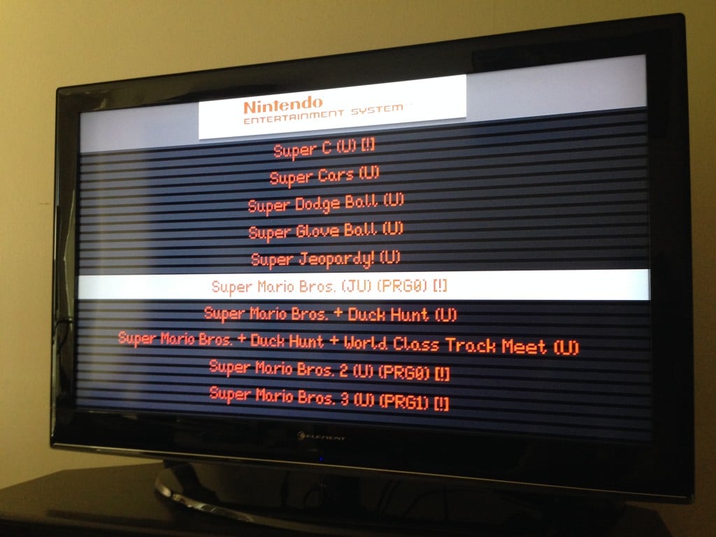
At this point, I’m dying to test out the system. Grabbed a controller and got sidetracked with Mario for a bit. Super Mario Bros looks awesome on a 24″ LED screen.
Next, I decided to mount another USB hub on top of the device. This would be for the game bay; I wanted to be able to access a mouse and keyboard if I needed to make any changes to the NES or modify it once it was complete, so I didn’t have to take it apart. Lookin good — all that’s left really is the rear power and HDMI ports.
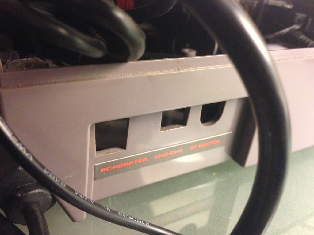
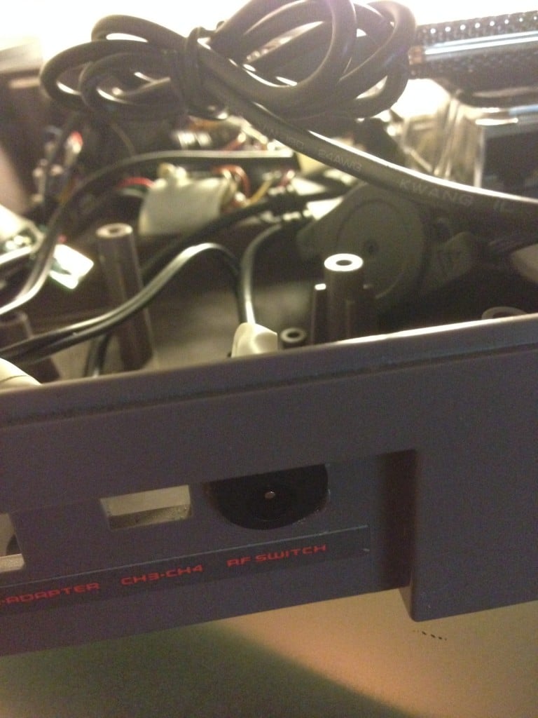
The power port in the back would be powering the USB hub, which in turns powers the entire device. I wanted to make use of at least one of these existing ports so I wasn’t drilling all sorts of additional holes in the back. The HDMI port is too wide, and would need to be mounted elsewhere.
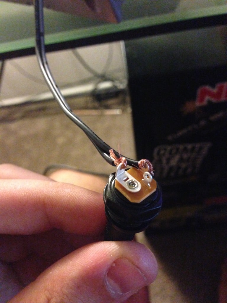
The power cord for my USB hub was a weird size, so I went with a much more common DC barrel size, and spliced it in to this panel mount I bought on Adafruit.com. This thing worked out beautifully — I found a matching DC power plug on Amazon that fit right in.
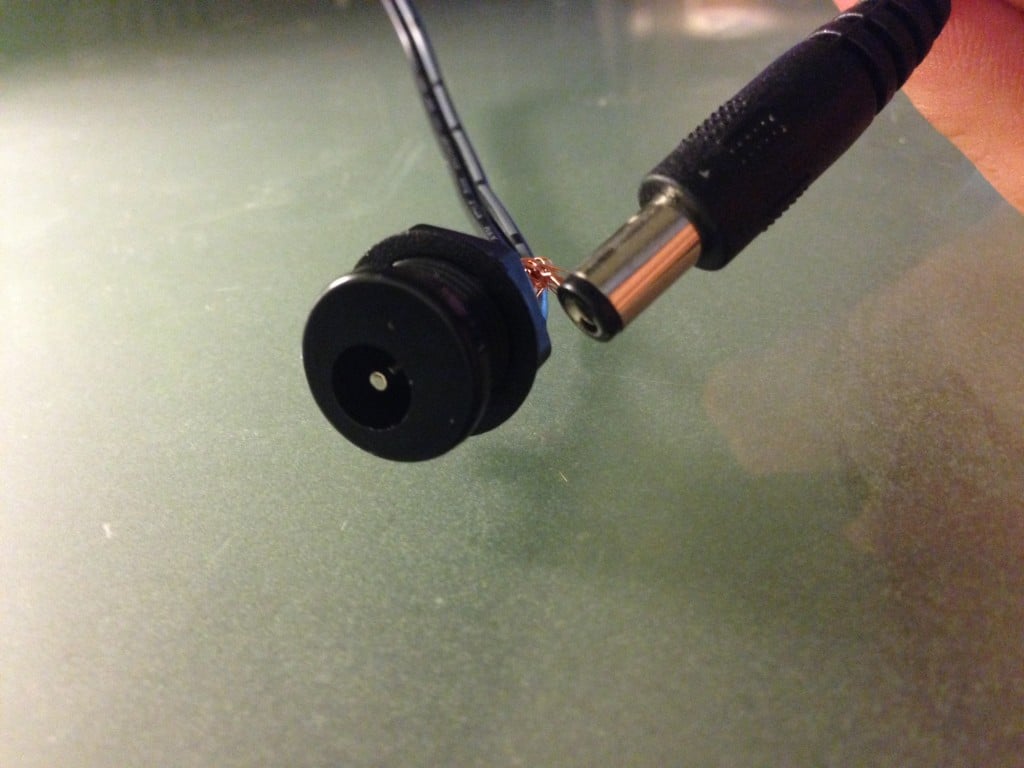
Another closeup of the DC barrel jack:
I dremeled out one of those little square port areas, and was able to mount the barrel jack in there. Looks clean.
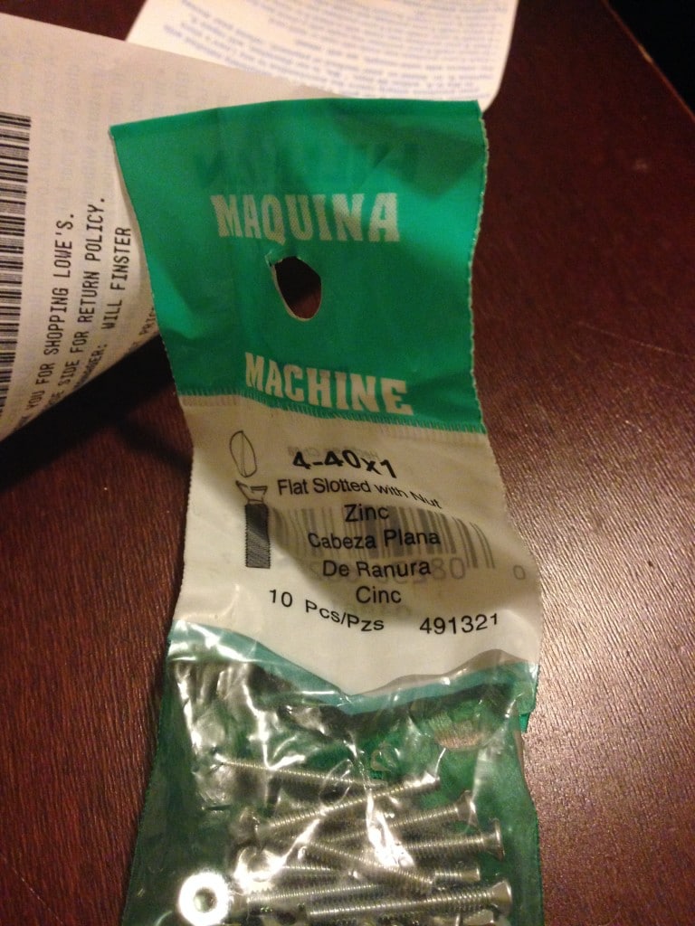
Next was the HDMI panel area; I bought the HDMI panel mount from Adafruit as well. This thing didn’t come with any screws, so I had to buy my own; I got lucky by finding a pair that fits at Lowes.
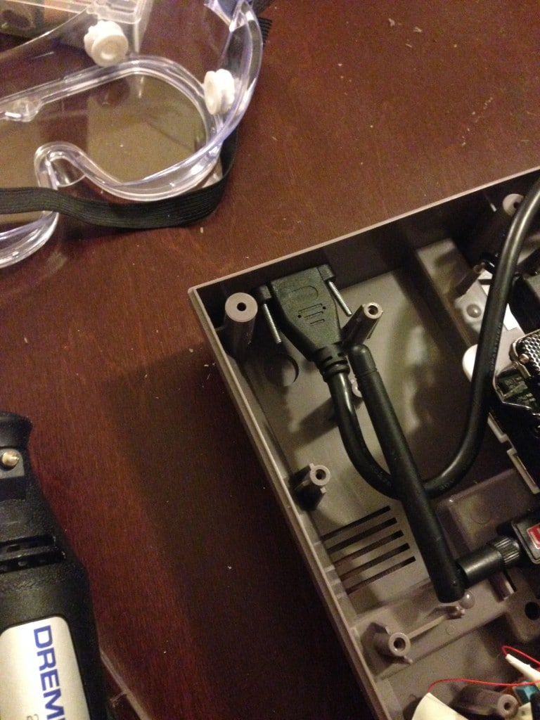
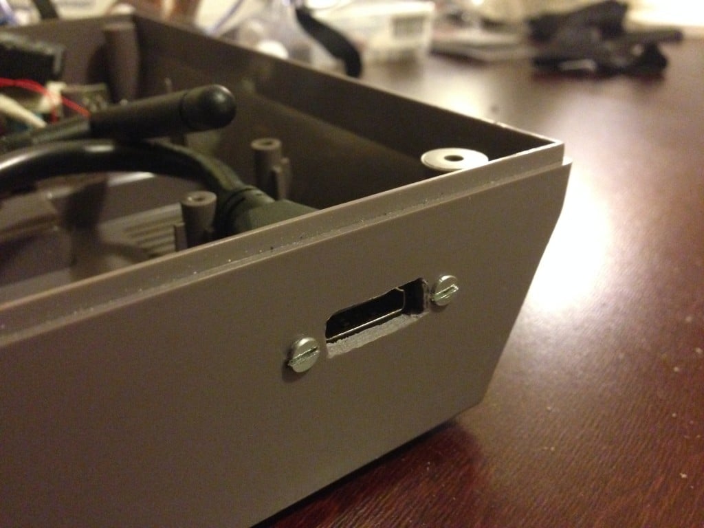
I had to carefully dremel out a little area for the HDMI plug, as well as two screwholes on each side to mount it to the enclosure. Here’s the finished product (top view):
Here’s a closeup of my dremel handiwork. I took my time with it, and went over it a few times with a grinding bit to make it as smooth as possible. I like how it came out.
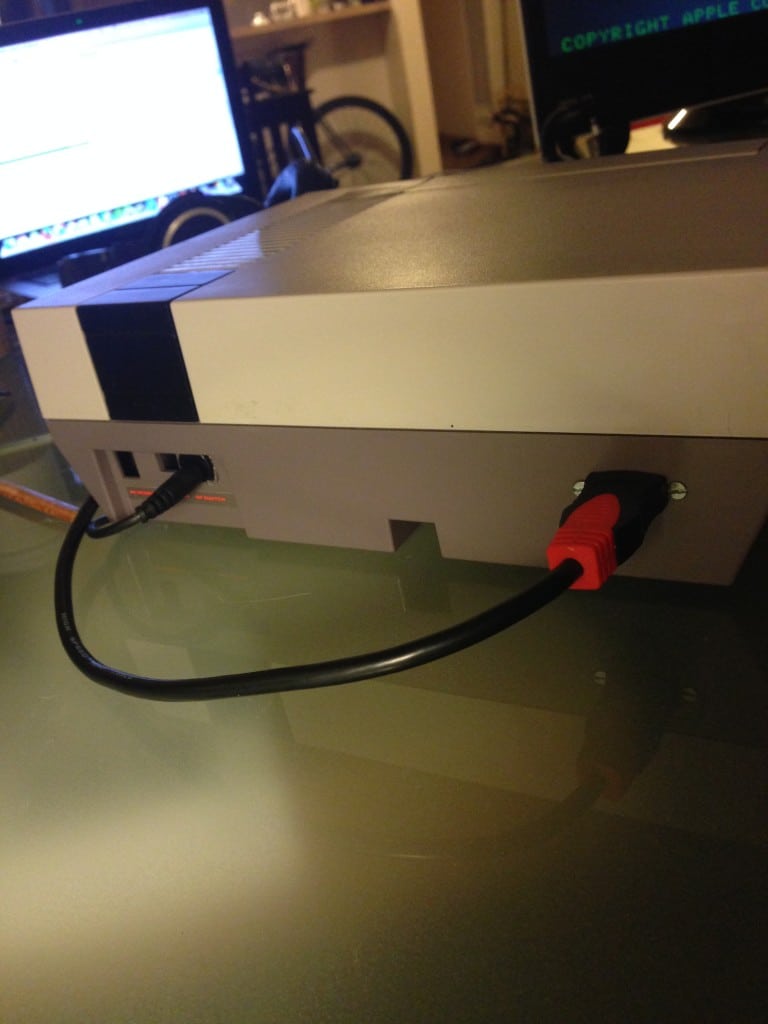
Here are the back power and HDMI ports, when plugged in. I’m very pleased with how clean and OEM-looking they look; exactly what I was going for. The entire system runs off of just a DC power plug and a HDMI cord, like any other console.
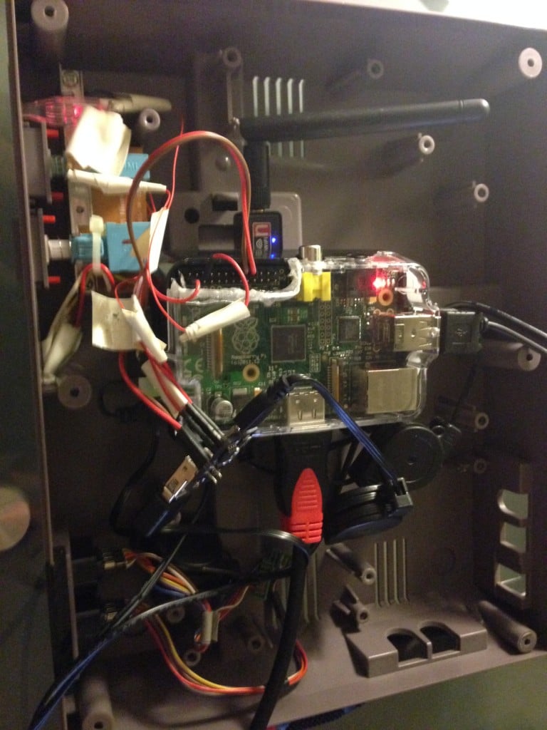
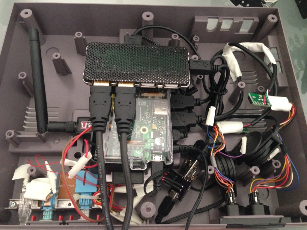
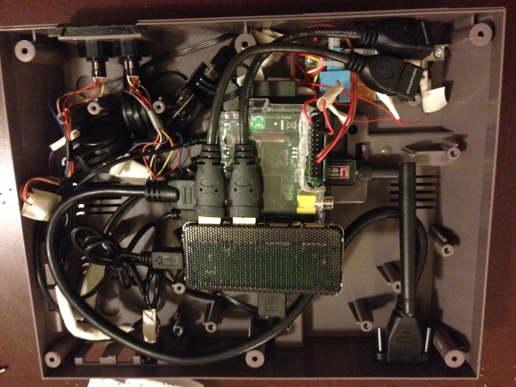
Before I button this thing up, here are some pictures of the final internals (top view):
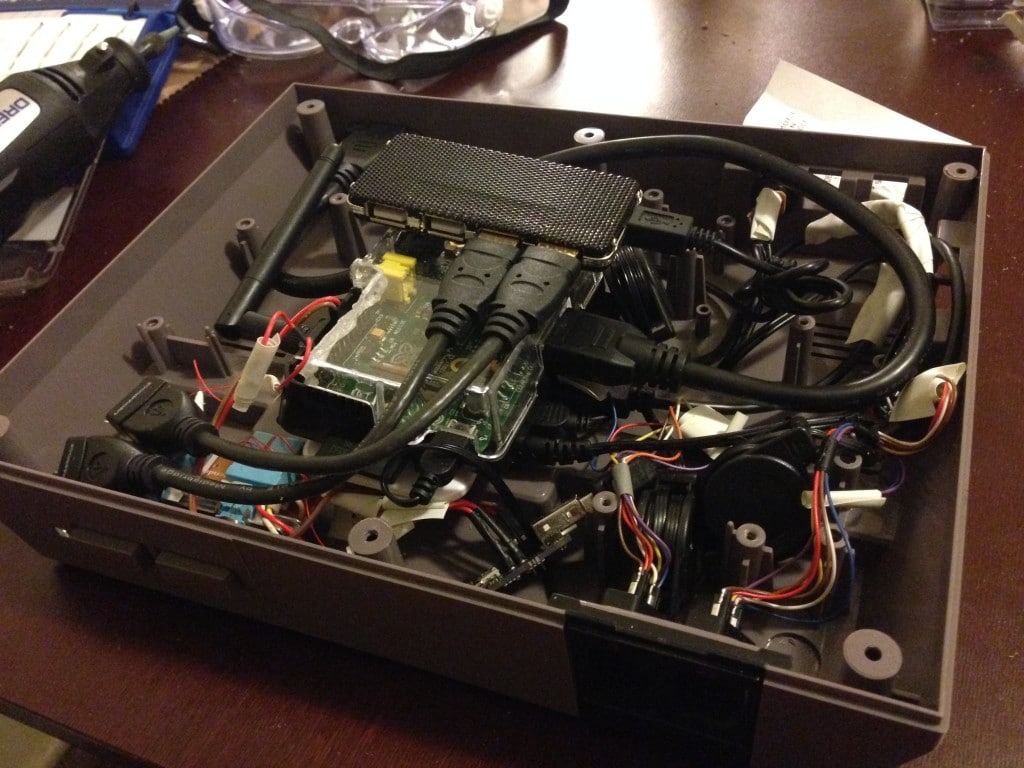
Here’s an angled view. What a beast!
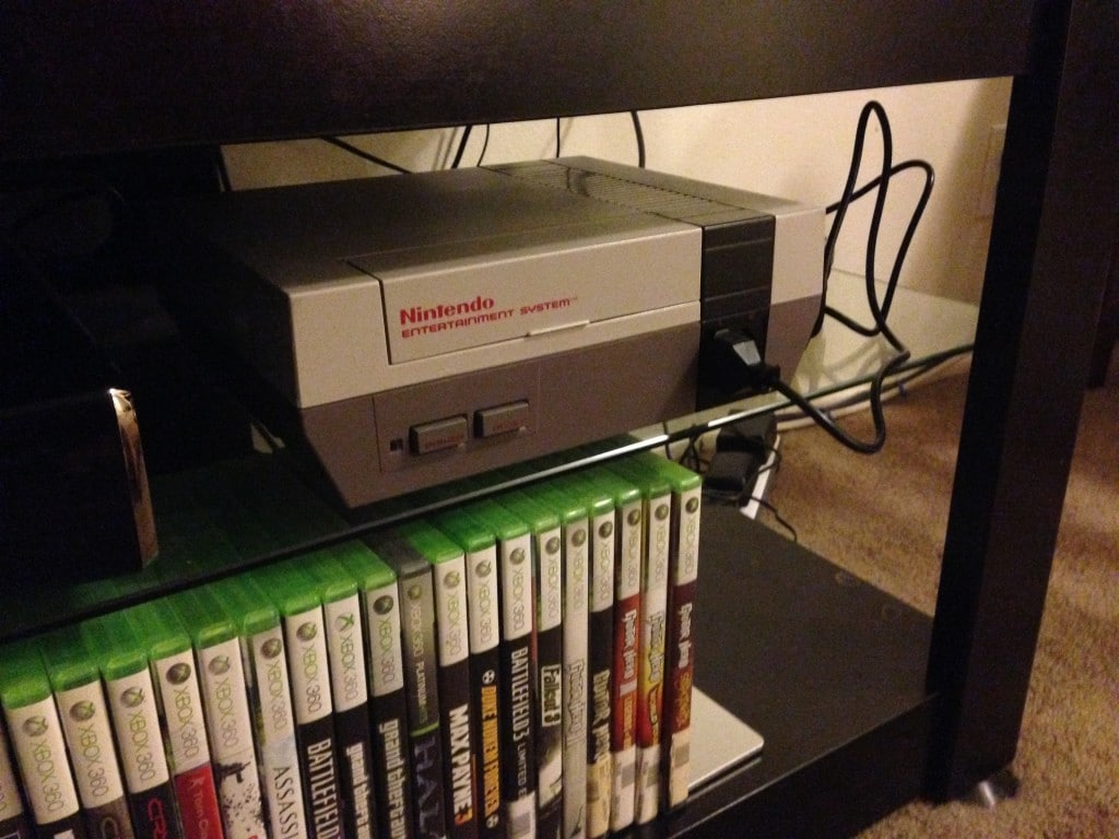
Here’s the finished product, at home in my media center, loaded up with every NES game ever made. Can you tell it’s modified from the outside?
Booting up
Still booting up
Game select screen. So many games!
Hope you enjoyed the photos! Drop a comment below if you have any questions about the build, and I’ll do my best to point you in the right direction.
EDIT:
A lot of people have been emailing me in about the “returning to menu” capability.
The controller’s start and select button reset to the menu; not the physical reset switch.
Here are the two lines that make “start” and “select” reset to the menu on a NES controller.
Navigate to: /home/pi/RetroPie/configs/all/retroarch.cfg
input_enable_hotkey_btn = “2”
input_exit_emulator_btn = “3”
Hope this helps. Good luck!
That’s awesome! I stick with my original NES, because this stuff is way over my head. I’m way jealous.
It’s not that bad actually. Just take your time and utilize Google a lot. I’m not an electrician or anything, but a lot of this stuff is documented on Google. You can learn a lot just from my thread; let me know if you decide to start on one, and I’ll do my best to help if you get stuck!
This is really cool! How long did it take you? and how much did it cost?
Thanks for the kind words! It took me about 6 months, mainly because I took a long pause inbetween areas of the project. The project ran around $600 in total I believe, not including larger things I needed to buy that I didn’t already have (a Dremel, a soldering iron, etc).
Nice build! I did a similar PI project myself. only differences would be I used a set of wireless Xbox controllers, No WIFI, and a different method of power. If I may link my YouTube competition video. http://www.youtube.com/watch?v=ZbCHS0SAIaA
How did you connect the Mausberry Circuit power switch from the Power/Reset on the NES to the Raspberry Pi? I only see the connection between the Mausberry and the GPIO, but not a direct connection between the NES and the Mausberry. How does that work? Thanks!
The Power/Reset switches wire up to the Mausberry switch. The mausberry switch then acts as a middleman for the Pi’s power, and the GPIO pins are simply to send the shutdown command. USB Hub > USB Cable > Mausberry chip > mini USB power cable > Raspberry PI
So when you press the power button, the signal is sent to the chip, which passes power through the chip to the Pi’s power source.
When you press it again to turn it off, the chip doesn’t let the power cut out suddenly; it sends a safe shutdown command via the GPIO pins, which lets the system gracefully shut down without harming any files.
I’m still trying to wrap my head around how that is wired based on your pictures.
Is this the switch you purchased?
http://mausberry-circuits.myshopify.com/products/shutdown-circuit-use-your-own-switch
If so, trying to determined if you soldered to the mausberry or if you purchased a different power switch.
Thanks for the great post and swift response to my question. Working to replicate your project, but that power switch part has me hung up.
I actually bought this one, and requested that there isn’t any rocker switch on it (just open pins for soldering): http://mausberry-circuits.myshopify.com/products/shutdown-switch-with-rocker
You solder wires from the leads underneath the NES switches to the gold-plated rings on the Mausberry Circuit. This photo displays this perfectly: http://i.imgur.com/ewxVdIW.jpg
What happens when you hit reset? Does it reboot the Pi? As in something is wrong. Reset? Or does it bring you back to say the rom screen?
It jumps back to the game select screen, it doesn’t reboot the Pi. Email me for more info 🙂
This looks awesome! Could you tell me what the black things are that plug into the GPIO and where to get them from? Is it necessary to take the power switches off to solder them? Could you give us a more detailed breakdown of how to get the power switch to work? The photographs are a good start but diagraphs would be really useful 🙂
Sorry if these questions are obvious or dumb, no experience with soldering or electronics whatsoever and every other blog I’ve found isn’t as detailed or helpful as yours.
Thank you!
For the GPIO pins, I just scoured the wall of my local electronics store and found some pre-stripped wires with those black pins; they work perfectly. Unfortunately I used all of them so I don’t have the packaging or the names of them.
Here’s a crude mockup of how the power switch is wired up: http://d.pr/i/nj1J/GSG8TSXo
Let me know if this helps!
Hi James. Nearly have everything up and running. Hey, did you have any challenges getting an NES controller mapped with emulationstation?
The only struggle was the getting the start and reset button to return to the game menu when pressed simultaneously. Everything else was relatively straight-forward once the controllers were wired up properly.
I added instructions to the end of this post how to get the “return to menu” functionality set up properly.